Input Specs
Fig. 2 shows a typical view of the Specs tab where you can specify the kind of filter to be designed and its specifications in the frequency domain:
- Response type (low pass, band pass, …)
- Filter type (IIR for a recursive filter with infinite impulse response or FIR for a non-recursive filter with finite impulse response)
- Filter class (elliptic, …) allowing you to select the filter design algorithm
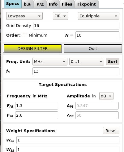
Fig. 2 Screenshot of specs input window
Not all combinations of design algorithms and response types are available - you won’t be offered unavailable combinations and some fields may be greyed out.
Order
The order of the filter, i.e. the number of poles / zeros / delays is either specified manually or the minimum order can be estimated for many filter algorithms to fulfill a set of given specifications.
Frequency Unit
In DSP, specifications and frequencies are expressed in different ways:
In pyfda, you can enter parameters as absolute frequency \({{f}}\), as normalized frequency \({{F}}\) w.r.t. to the Sampling Frequency \({f_S}\) or to the Nyquist Frequency \(f_{Ny} = f_S / 2\) (Fig. 3):
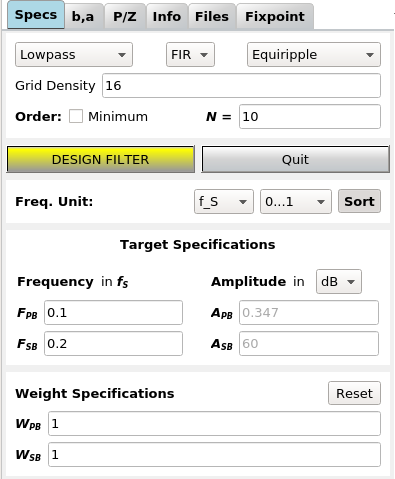
Fig. 3 Displaying normalized frequencies
Amplitude Unit
Amplitude specification can be entered as V, dB or W; they are converted
automatically. Conversion depends on the filter type (IIR vs. FIR) and whether
pass or stop band are specified. For details see the conversion functions
pyfda.pyfda_lib.unit2lin() and pyfda.pyfda_lib.lin2unit().
Background Info
Sampling Frequency
One of the most important parameters in a digital signal processing system is the sampling frequency \({\pmb{f_S}}\), defining the clock frequency with which the registers (flip-flops) in the system are updated. In a simple DSP system, the clock frequency of ADC, digital filter and DAC might be identical:
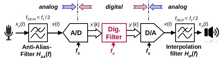
Fig. 4 A simple signal processing system
Sometimes it makes sense to change the sampling frequency in the processing system e.g. to reduce the sampling rate of an oversampling ADC or to increase the clocking frequency of an DAC to ease and improve reconstruction of the analog signal.
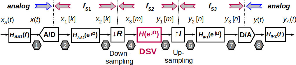
Fig. 5 A signal processing system with multiple sampling frequencies
Aliasing and Nyquist Frequency
When the sampling frequency is too low, significant information is lost in the process and the signal cannot be reconstructed without errors (forth image in Fig. 6) [Smith99]. This effect is called aliasing.
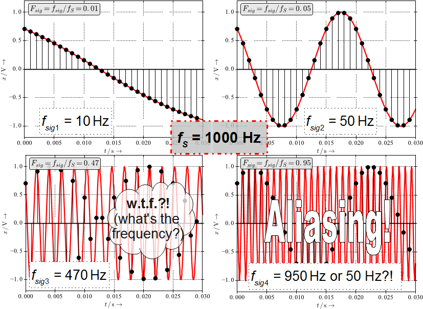
Fig. 6 Sampling with \(f_S = 1000\) Hz of sinusoids with 4 different frequencies
When sampling with \(f_S\), the maximum signal bandwidth \(B\) that can represented and reconstructed without errors is given by \(B < f_S/2 = f_{Ny}\). This is also called the Nyquist frequency or bandwidth \(f_{Ny}\). Some filter design tools and algorithms normalize frequencies w.r.t. to \(f_{Ny}\) instead of \(f_S\).
Development
More info on this widget can be found under input_specs.