Fixpoint Specs
Overview
The Fixpoint tab (Fig. 14) provides options for generating and simulating discrete-time filters that can be implemented in hardware. Hardware implementations for discrete-time filters usually imply fixpoint arithmetics but this could change in the future as floating point arithmetics can be implemented on FPGAs using dedicated floating point units (FPUs).
Order and the coefficients have been calculated by a filter design algorithm from the pyfda.filter_designs package to meet target filter specifications (usually in the frequency domain).
In this tab, a fixpoint implementation can be selected in the upper left corner (fixpoint filter implementations are available only for a few filter design algorithms at the moment, most notably IIR filters are missing).
The fixpoint format of input word \(Q_X\) and output word \(Q_Y\) can be adjusted for all fixpoint filters, pressing the “lock” button makes the format of input and output word identical. Depending on the fixpoint filter, other formats (coefficients, accumulator) can be set as well.
In general, Ovfl. combo boxes determine overflow behaviour (Two’s complement wrap around or saturation), Quant. combo boxes select quantization behaviour between rounding, truncation (“floor”) or round-towards-zero (“fix”). These methods may not all be implemented for each fixpoint filter. Truncation is easiest to implement but has an average bias of -1/2 LSB, in contrast, rounding has no bias but requires an additional adder. Only rounding-towards-zero guarantees that the magnitude of the rounded number is not larger than the input, thus preventing limit cycles in recursive filters.
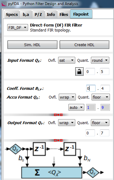
Fig. 14 Fixpoint parameter entry widget
Typical simulation results are shown in Fig. 15 (time domain) and Fig. 16 (frequency domain).
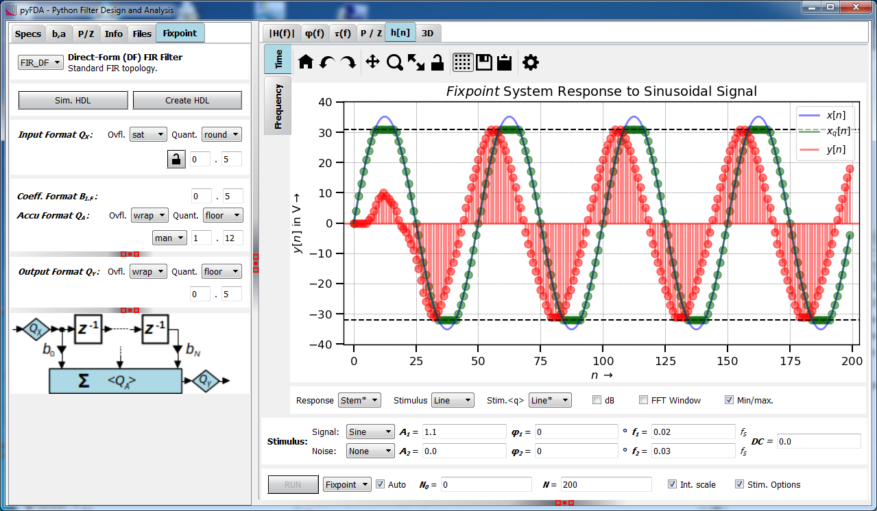
Fig. 15 Fixpoint simulation results (time domain)
Fixpoint filters are inherently non-linear due to quantization and saturation effects, that’s why frequency characteristics can only be derived by running a transient simulation and calculating the Fourier response afterwards:
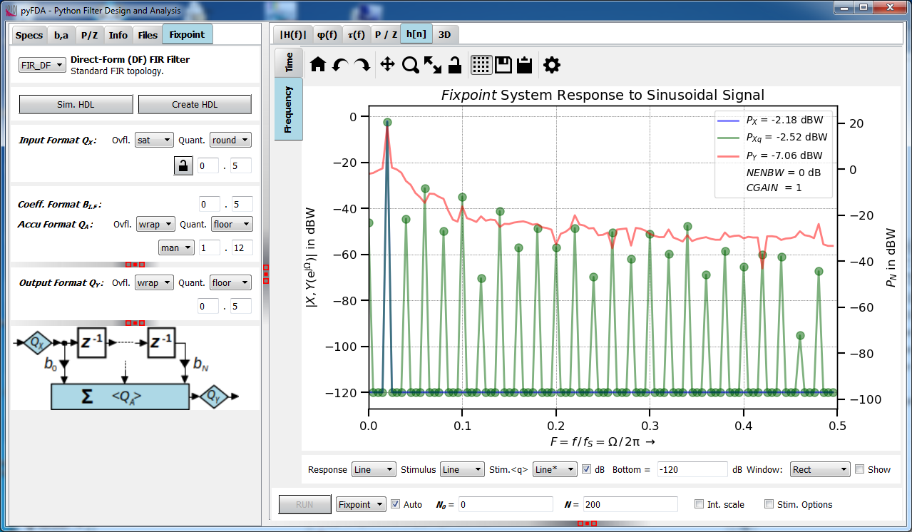
Fig. 16 Fixpoint simulation results (frequency domain)
Configuration
The configuration file pyfda.conf lists the fixpoint classes to be used,
e.g. DF1 and DF2. pyfda.tree_builder.Tree_Builder parses this file
and writes all fixpoint modules
into the list fb.fixpoint_widgets_list. The input widget
pyfda.input_widgets.input_fixpoint_specs.Input_Fixpoint_Specs constructs a combo box from this list
with references to all successfully imported fixpoint modules.
The currently selected fixpoint widget (e.g. DF1) is imported from
pyfda.fixpoint_widgets together with the referenced image.
Development
More info on this widget can be found under input_widgets.input_fixpoint_specs.